
A warehouse drawing may show an aisle that meets a robot’s published width requirement. On site, a rack guard projects into the turning area, a tote rim catches the shelf beam, or the picking station cannot clear returned containers quickly enough. Each problem can interrupt CTU operation even when the robot itself is functioning normally.
Planning a Carton Transfer Unit (CTU) deployment therefore starts with a measured handling route: loaded tote, rack opening, pickup position, travel aisle and workstation. The checks below help warehouse engineers and project teams discover physical constraints before purchasing equipment or committing to a layout.
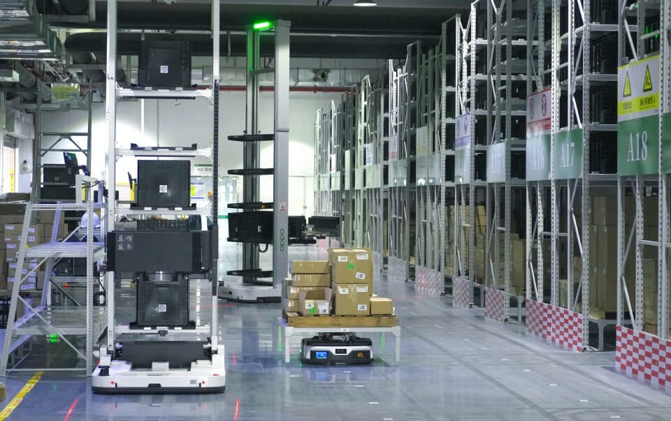
Figure 1. Automated tote handling beside multi-level warehouse storage racks.
Build a Tote Register That Reflects Actual Loads
A CTU is intended for compatible totes or cartons, not general pallet lifting. Wesar’s CTU robot range includes different handling arrangements. Choosing one begins with a representative set of the containers it must retrieve.
Measure the loaded carrier, including the parts that stick out
Record external length, width and height rather than the nominal internal volume. Include the rim, handles, lid, labels and the highest permitted contents. Measure samples from each container supplier and include worn or slightly distorted bins that are still allowed in daily use.
Weight needs the same treatment. Record the empty weight, maximum loaded weight and where the center of mass may shift. A long, uneven load may be more difficult to handle than a compact load of the same mass. Confirm the intended clamp-contact surfaces and whether a barcode can be read without moving the tote.
The carrier register should contain at least five fields: carrier type and ID convention; maximum outside dimensions; maximum gross mass; permitted grip faces; and any lids, overhangs or damaged-bin rejection rules. A SKU list alone does not supply these handling details.
Do not confuse vehicle load with actuator load
For the TP5-50DC, Wesar lists a 300 kg robot-rated load but a 50 kg execution-structure load. The 300 kg figure is not the permitted mass of a single tote lifted by the clamp. Carrier suitability must be checked against the handling mechanism and the complete approved robot configuration.
Check the Rack as an Extraction Space, Not Just a Height
Start by recording the actual height of each pickup position. Then measure the clear shelf opening, beam projection, storage depth and free space above and beside a loaded tote. The critical question is whether the handling mechanism can engage the carrier and remove it along its required path without striking the rack.
The published TP5-50DC specifications list a 200-4,000 mm picking-height range and a 600 x 400 x (100-330) mm carrier-size range. The separate TP5-50DC-B parameter table lists 300-2,300 mm picking height and 600 x 400 x 300 mm cargo dimensions, with customization noted. These are model-specific starting points, not interchangeable specifications or a guarantee of compatibility with any rack.
Test the difficult shelf locations first
Do not demonstrate only a convenient mid-height slot. Use the real loaded container at the lowest intended position, the highest intended position and a shelf with the tightest beam clearance. Check that the pickup location is repeatable when bins are placed slightly off-center within the operating tolerance agreed for the project.
Single-deep versus double-deep changes the retrieval sequence
The TP5-50DC specification describes a single-deep clamping structure. A double-deep layout introduces additional questions: can the robot reach the rear position, must the front tote move first, and where will displaced totes wait? A rack that holds more bins per square metre is not automatically a faster or compatible storage design. Confirm the precise actuator arrangement before designing around rear-position access.
Draw Every Turn, Stop and Recovery Position
Straight-aisle width is only one part of the travel envelope. The TP5-50DC-B page lists a 1,000 mm aisle width and a 1,865 mm rotational diameter. The separate TP5-50DC page lists 1,050 mm and 1,600 mm respectively. The smaller published aisle number does not mean that every aisle intersection, turn or passing point can be built to that width.
Mark the robot’s full route on a scaled, measured drawing. Include:
Straight runs and row-end turns, including the load and robot’s occupied space during turning.
Rack feet, protective barriers, columns, doors, floor transitions and temporary pallet parking.
Approach and stopping positions for each rack face and each workstation handoff.
Pedestrian crossings, emergency access and a safe route for personnel to recover a stopped robot.
Charging, waiting and maintenance positions that may occupy a shared aisle during a busy shift.
Walk the route with the intended site team. A nominally clear aisle can become unusable when a door is open or goods are staged at its end. Keep safety clearances and operating procedures subject to the site’s engineering and risk assessment; catalogue aisle dimensions are not safety approvals.
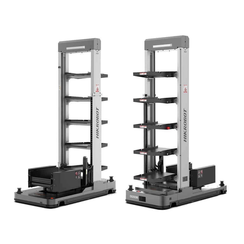
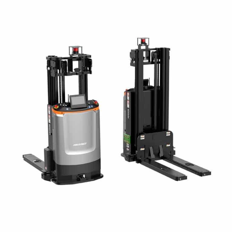
Figure 2. Wesar TP5-50DC-B CTU handling configurations.
Size the Picking Station Before Estimating Robot Count
A tote arriving at a station is not automatically ready for the next robot. Someone may still need to identify it, scan the item, pick a quantity, confirm a shortage, close the tote and release it for return. Measure this entire station cycle, not simply the robot’s arrival time.
For illustration, if one station takes 60 seconds to process and release each tote, its ideal, uninterrupted ceiling is 60 totes per hour. That is a calculation for the station, not a Wesar CTU throughput claim. Actual output will be lower when the mix of orders, breaks, missing stock and return traffic is considered. A fleet capable of arriving faster will only create a queue in front of that station.
Where more than one station is planned, record each station’s product mix and release time separately. Determine where a delivered tote waits, which signal authorizes the next arrival and whether a returning tote can block an incoming one. Wesar describes layout, routes, task parameters and order structure as inputs to its iWMS-1000 business simulation; any predicted capacity still needs checking with the customer’s representative order data.
Test the Peak Workload, Including Empty and Return Moves
Average daily order volume can conceal a short, difficult operating peak. Collect order lines in hourly or shorter time buckets, distinct totes requested, return and replenishment movements, actual travel distance, station dwell time and charging interruptions.
Then review one complete tote cycle: the robot receives the job, reaches the rack, extracts the bin, travels to the station, waits for the handoff, returns or relocates the bin, and becomes available again. Count waiting and empty travel. A site that requires many returns to distant racks may need a different fleet size from one with the same number of picks near the stations.
Before increasing the fleet, determine which resource becomes saturated first: rack access, aisle intersections, station labor or charging availability. More robots will not remove a station bottleneck.
Use a Site Acceptance Sheet With Pass/Fail Evidence
Commissioning should verify the hardest permitted conditions, not a single successful test run. Agree on the following evidence with the integrator before operational handover:
|
Interface to verify |
Test with actual site equipment |
Evidence to record |
|---|---|---|
|
Tote and gripper |
Heaviest approved bin and edge-case tote dimensions |
Carrier ID, load, grip result, reason for rejection |
|
Rack access |
Lowest, highest and tightest intended shelf positions |
Shelf ID, clearance, extraction and return result |
|
Aisle movement |
Row-end turn, cross-aisle conflict and obstructed route |
Route ID, stop or recovery behavior, intervention |
|
Workstation handoff |
Repeat arrivals during a representative order peak |
Arrival, scan, release and queue timestamps |
|
Inventory handoff |
Successful return plus one failed pickup |
Actual bin location and corresponding WMS record |
Specify who signs off each result and what requires re-testing after a shelf, container or software change. Acceptance is complete only when the physical tote and the warehouse record agree on where it ended up.
Conclusión
A CTU deployment succeeds or fails at its interfaces: the real carrier must fit the handling mechanism, the rack must allow extraction, the full route must remain usable, and the station must clear containers at the required rate. Measure these conditions early, then prove them with loaded totes and a peak-period trial. Published product specifications can shortlist a model; they cannot replace a site acceptance test.
Preguntas frecuentes
1. Should I measure the tote with its lid and contents in place?
Yes. Use the maximum allowed outside dimensions and gross mass. Rims, lids and contents that protrude can change the available gripping and shelf clearance.
2. Can the TP5-50DC lift one tote weighing 300 kg?
No. Wesar lists 300 kg as its robot-rated load but 50 kg as the execution-structure load. The selected clamp’s permitted payload governs the individual carrier handled by that mechanism.
3. Do the TP5-50DC and TP5-50DC-B have the same picking height?
No. Their published parameter tables list different ranges. Use the exact model specification and test the highest and lowest positions in the proposed installation.
4. Is a 1,000 mm aisle enough for all CTU turning movements?
No. A published aisle dimension is not a complete turning or safety-clearance drawing. Verify the selected robot’s rotational envelope at every intersection and handoff point.
5. What changes if the racks are double-deep?
The system may need a compatible reach mechanism and a rule for accessing rear totes when front locations are occupied. Confirm both before changing the storage layout.
6. Which measurement is most useful for estimating station capacity?
Time the complete tote handling cycle, from arrival through scan, picking, release and removal. Multiply by the number of working stations only after allowing for realistic interruptions.
7. What should trigger re-testing after CTU commissioning?
Changes to tote dimensions or weights, shelf geometry, station handoff points, travel routes or WMS location mapping should trigger an impact check and targeted re-test.






 Spanish
 English
 Russian
 Chinese
 Japanese
 Italian
 Korean
 Arabic
 French
 German